

Probably the biggest dilema – the chainplates. These are one of the most important structural parts of a sailing vessel. The chainplates on Boundless were original, and used a not uncommon (at the time) method of attachment; they were glassed right into the side of the hull, prior to the furniture being built into the boat. While the intent was that they were ‘maintenance free’, the fact was they could not be inspected or maintained at all below the level of the deck.
We knew at the time of buying the boat that this was a potential ‘issue’. Although the Passport 42 is generally overbuilt and there had not been any reported failures that we were aware of, the fact that this important structural element was now 36 years old, and as there were also signs of rust stains at the rubrail at the point of the chainplates, it was a concern.
Our Covid 19 induced ‘wait and see’ period, pending cruising grounds opening south of Mexico, and, with excellent resources available in La Paz, this seemed like a good time to ‘bite the bullet’ and tackle this issue, at the same time as we dealt with the other significant issue with the boat; the teak decks.
The plan:
- Replace the eight (four each side) chainplates that support the shrounds
- Replace the backstay chainplate
- Replace the deck fitting and backing plate system for the inner forestay (staysail).
- Make modifications to the existing stem fitting to create a stronger attachment point for the forestay, as well as an attachment point for the asymmetrical (and also extend the anchor roller).
We had heard of Sergio Galindo and his stellar reputation when we were here in La Paz last year, and were extremely fortunate to get connected with him for this project. Not only was he clearly well qualified (there were two other boats in the same marina that had received recent chainplate replacements with Sergio), but he was a total pleasure to work with. In addition to the chainplates, we also had him undertake a number of other stainless steel projects – see the ‘Stainless Bling’ post.
1. SIDE (SHROUD) CHAINPLATE REPLACEMENT

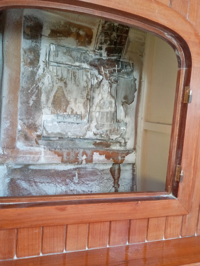
Preparing the area for the guys to come in, we took off the doors and removed the shelves from the behind the salon sofas. The chainplates are located behind the staving at the rear of the built in teak furniture.

Getting to the chainplates will require quite a bit of destruction, but all of it is located inside cupboards, with the exception of the centre section which is bookshleves, generally filled with books. The rear of it is all these areas is usually unseen. As long as we do not damage the front of the cabinetry, the ultimate appearance should be almost exactly as it was.

A carpenter removed all of the staving and other interior sections of the cabinets to reveal the inside of the hull.


With the staving removed, the chainplates were visible as ‘H’ shapes glassed into the side of the hull. Visible here also is a piece of bonding wire also glassed in.

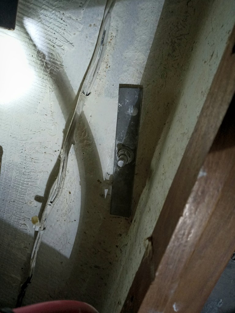
The chainplates are flat up until a few inches below the deck when they are bent in, and screwed to a wedge shaped block filler piece. Visible on this one is brown staining around the main bolt, and also below the chainplate, under the glass fiber.
We drilled a small hole under this chainplate, and coming back a few hours later, there was a mysterious brown liquid leaking out.

The plan is to complete the project in pairs of chainplates to avoid the requirement to drop the mast. The first chainplate was removed on its own, as an investigation into how to best attack the extraction. Note the center bolt that attaches through the chainplate to a bolt head that will be accessed underneath the rubrail. This is the only bolt through the chainplate. The system relied on the glass embed to secure the chainplate. The lower nut that is visible is just for attachment of a bonding wire and does not pass through the chainplate.

After completely cutting out the chainplate, it was pulled through the deck, and taken out.
Note that this chainplate sits neatly within the cabinet, and at this stage the side wall of the cabinet is still there. This would later be removed to give free access to remove the adjacent chainplate.
This particular chainplate was completely dry, and there was no particular sign of moisture having penetrated down into the glass fiber.

Where the chainplate came through the deck as an attachment point for the shroud. While these are raised in the GRP mold, they rely entirely on sealant to stop any water travelling down the chainplate.
With the first chainplate extracted, the process of removing the others was started.
It was evident as these were exposed, that there was indeed water ingress in the chainplate ‘cavity’, clearly seen as moisture run-off in these photos.
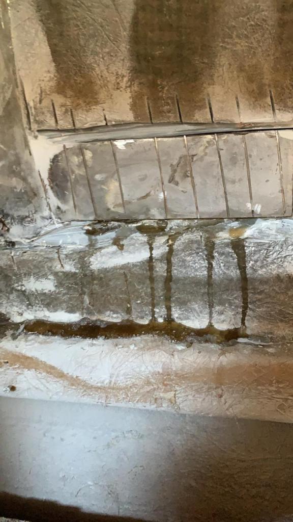
Another of the chainplates weeping.
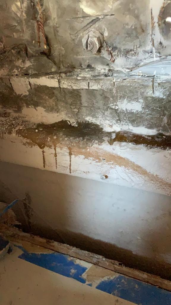
And again.

The forward starboard chainplate was not immediately accessible, and would require destroying part of the bulkhead forward of the three cabinet sections into the cupboard located by the cabin heater. Here it is mid-destruction – you can see where the chainplate is well buried right in line with the bulkhead.
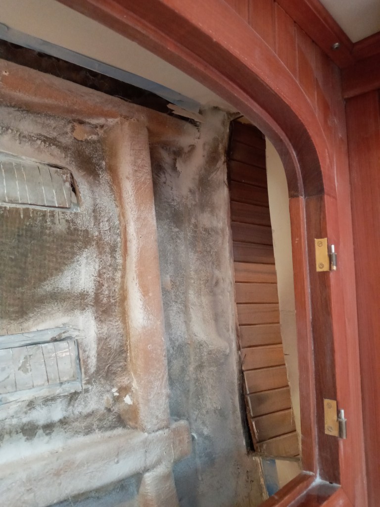
The forward port chainplate required breaking through the bulkhead into cabinet behind the sink in the head.
This means that we will need to do a bit more reparative carpentry when putting the boat back together.

The first chainplate removed, this is the area that remained. It is clear where the chainplate was embedded in bonding material and then glassed over. The inside skin of the hull layup is visible behind where the chainplate was.
Visible also is the remains of the (single) bolt that connected through the hull at the point of the rub rail. The bolt head was behind the rub rail, and was the cause of staining on the exterior at this point.

This shows the wedge section which leads the chainplate through the deck at the angle. These were well encased in glass and do not appear to have been affected by moisture.
The chainplate was connected to the wedge section by small screws.

Two of the chainplates after removal. (Note the one on the right was cut during removal).

Another view of one of the chainplates shows the (larger) hole for the rubrail bolt, and three small holes for screws to the ‘wedge’.

One of the bolts etracted from the rub rail – this bolt is severely corroded, and the cause of staining on the hull and rub rail wood on the exterior.

The rub rail, with a section removed, and the bolt extracted.
Our intention is to paint the rub rail grey to match the hull, and install a stainless strip along, so we are not too concerned about removing sections in this fashion. This avoids the significant task associated with removing the rub rail entirely.
Note: keeping the varnish looking good on the rub rail in the tropics is a huge challenge, and we think painting it (with a two part paint) is likely to last much longer than varnish. We will add a stainless steel strip along the length which should look good, and match the stainless steel ‘eyebrow’ installed previously on the cabin top.

The old chainplates came through the deck on raised ‘plynths’ – this is one with the chainplate removed. We decided to get rid of these ‘plynths’ and create a flat base for the new chainplates.
This would allow us to put a more generous deckplate on the chainplate at the point it goes through the deck. Also, with the deckplate welded to the chainplate it will be much less likely to allow water intrusion than the original system, that relies on butyl tape to prevent water running down the rigging entering into the chainplate.
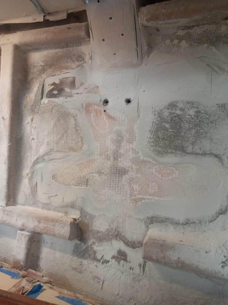
With the chainplates removed from the interior, the area was ground flat. This is the location of the port side double chainplate.

Another chaiplate area ground flat. There is still a good covering of glass around the ‘wedge’ at the top and the guys were careful to avoid grinding into the original hull layup.

This is the Starboard double chainplate area. You can see that required additional filling to create flat base for the new chainplate.

At this point we tested the new chainplate. This is the first test chainplate, with the chainplate bent to match the old one, but this chainplate is about 6 inches longer than the original. The intention was to create a longer chainplate for additional strength, but when testing it we found a) it was too long to install from inside without destroying more of the furniture, and b) it was just ridiculously large, and would have required a massive backing plate on the exterior. We opted for a shorter chainplate, retaining eight bolts in the double chainplates, and four in the single, but more closely placed than shown here.

We had also spec’d a heavier plate than the original, going from 1/4 inch to 3/8 inch 316L stainless steel. This shows one of the new chainplates held against one of the old ones. They feel substantially more robust than the original (which have been fine for 36 years).

Test fitting the new shorter chainplate, the same size as the original.

After grinding the interior areas flat, they recieved two layers of heavy duty glass mat for additional strength, and then additional West System filler material where required to create a flat seat for the new chainplate.
They were then sanded flat and painted white.


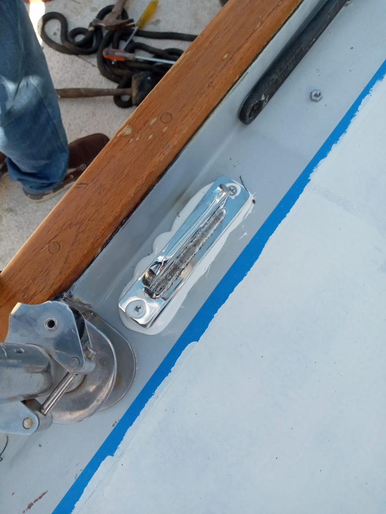
With the new chainplates made, they were test fitted and the deck footplates were spot welded in the correct position.
Note the area of the deck where the deckplate sits had been ground flat, filled, primed and then painted to match the gelcoat.
(Note the rest of the deck, where the teak decks were removed is now ready for primer.)

This shows the ‘before’ in the foreground – note the raised plynth and screwed on cover plate, and the ‘new’ in the background, with the plynth removed.
Note at this point we also checking to see that the angle of the new chainplates is correct, ready to accept the turnbuckles.
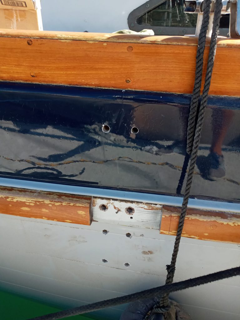
With the new chainplates being test fitted, it was time to drill the new bolt-holes. The original bolt holes through the rub rail were used again, and six (for this double chainplate) additional holes were drilled.

Steel spaces were inserted and fixed with epoxy into the holes. The reason for this is
a) As the deck is cored with foam, to prevent any possible collapsing on either the inner or outer skin once the interior chainplates were tightened again the exterior backing plates. (highly unlikely!).
b) To seal the holes and prevent water entering into the core of the hull, in the unlikely event it were ever to work its way passed the backing plates.

The spaces were trimmed to size

This shows the area ready to accept the first two chainplates. The tape is covering the inside of the holes with the spacers newly installed, while the epoxy cures.

The chainplates now have the deckplates welded on, and are installed with the bolts.

One of the single chainplates now installed. the excess bolts have been ground down.
Also visible is a small tapped hole (between the lower two bolts) ready to accept a machine screw securing a bonding wire.

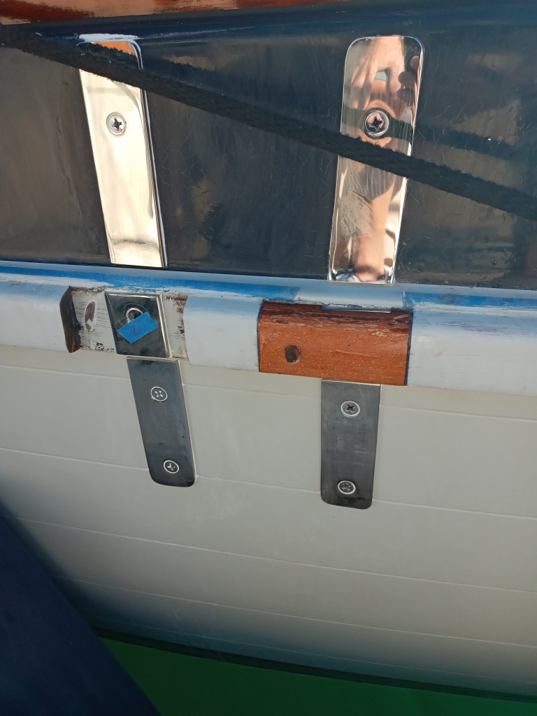
Installing the backing plates on the exterior.

They were bedded with (ample amounts of) 3M 5200.
The deck plate is also bedded with 5200, and through bolted to washers under the deck.
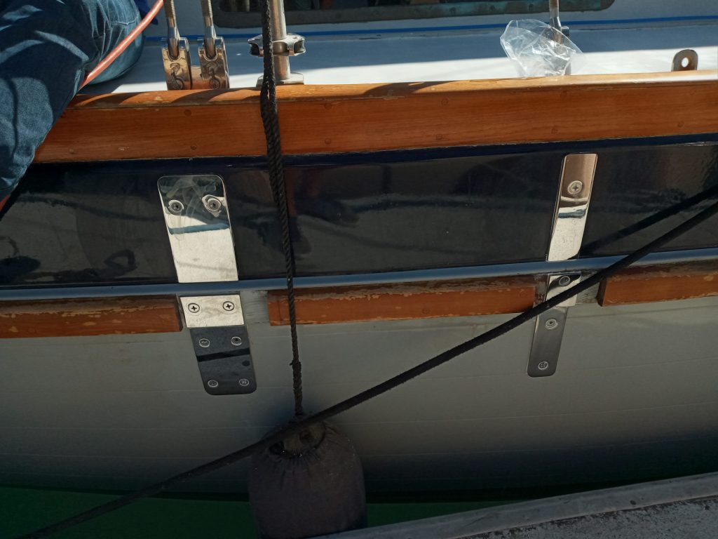
The first two chainplate backing plates installed. Three individual plates are currently visible for each chainplate. The center section will eventually be covered with the rub rail.

All four chainplates and backing plates installed.
Starting to replace the sections of rub rail.
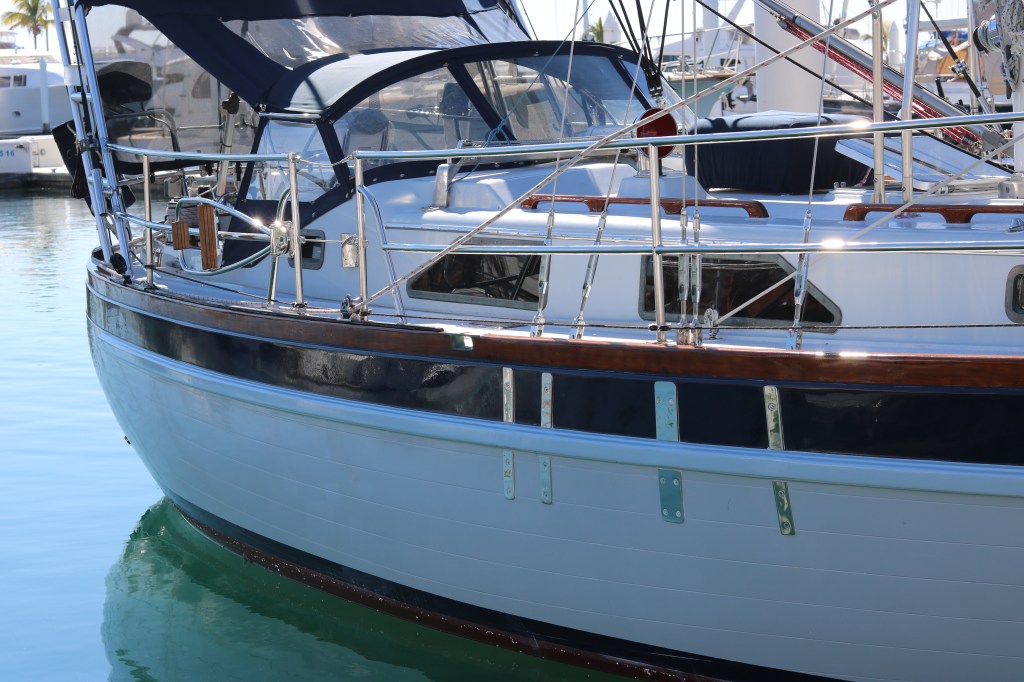
From the exterior, the result is esthetically pleasing, with just the backing plates showing. We chose to ‘paint out’ the rub rail, which was previously varnished, and we are pleased with the way it all looks.
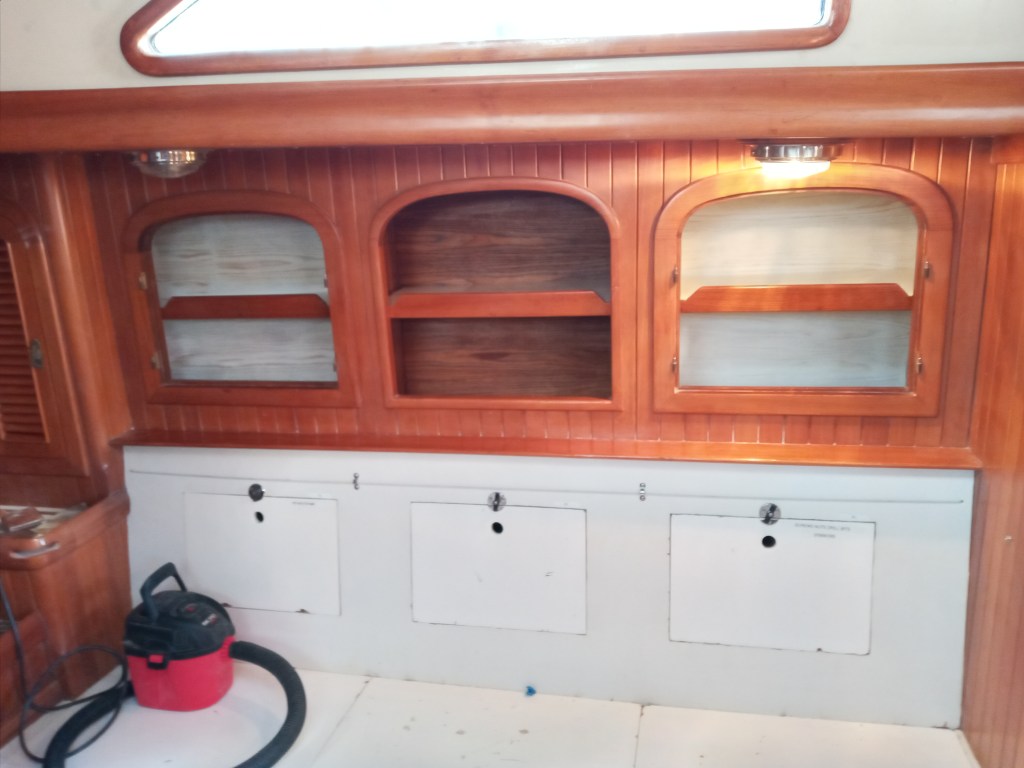
The carpenter reinstalled the interior of the cabinets. Note that the previous staving is replaced with screwed on panels that can be removed, to allow future inspection of the chainplates.
Note: painting and varnish not completed in this picture. Also, the doors are yet to be installed on the two side (white) alcoves.
With the books back in place, there is hardly any trace from the interior that the project ever happened.
2. Backstay Chainplate

This was a relatively easy operation replacing the backstay chainplate ‘like for like’, except the replacement plate is 3/8″ plate as opposed to the original 1/4″.
3. Staysail Stay Chainplate

BELOW – BEFORE: Having removed the interior headliner (not so easy, the headliner was installed prior to the interior furniture, so needed to be cut), we were somewhat surprised to see just a small under-deck backing plate for the staysail. This was about 4″ square, the same size as the corresponding deck plate above.
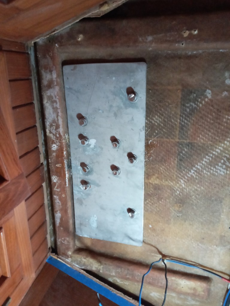
BELOW – AFTER: We replaced the small backing plate with one that was much larger.
Extending the above-deck fitting forward (the front of triangle), allowed us to add an additional fixing forward, in the anchor locker, on the forward side of the bulkhead separating the forward cabin from the anchor locker.
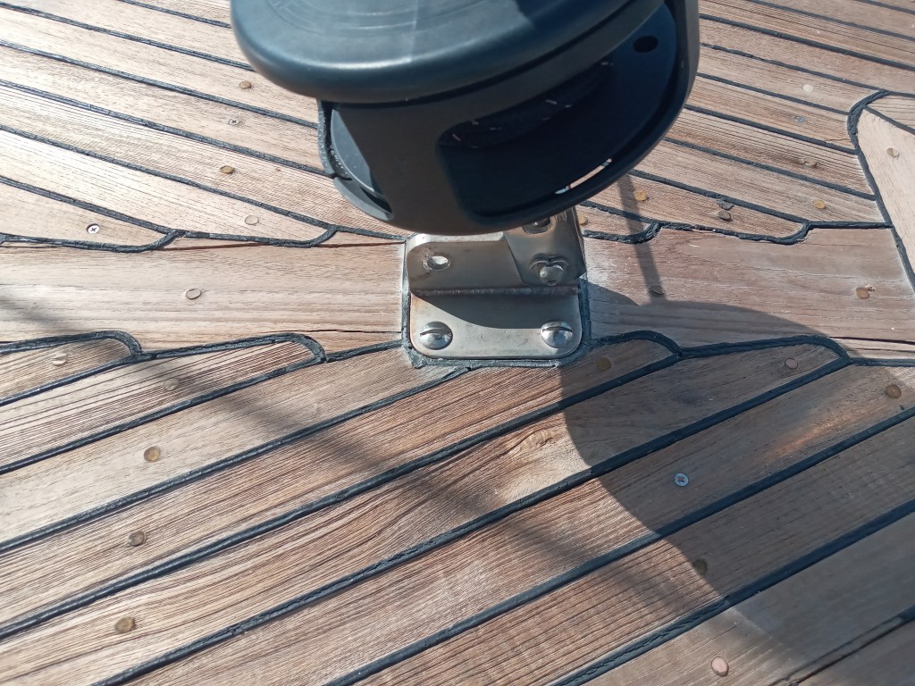
ABOVE DECK – BEFORE: The fitting was a smaller (approx 4″ square) anchor for the staysail.

ABOVE DECK – AFTER: We increased the size of the fitting itself, and added a samson post.
(Note the deck has not yet received the KiwiGrip finish in this photo)
4. Bow Roller & Forestay/Stem Fitting

BEFORE: The original stem fitting. The objective of this part of the project was to :
- Extend the bow roller by 6″ to better hold the 65# Mantus anchor we currently use as our primary
- Strengthen the fitting by reinforcing the area where the forestay attaches, as well as adding additional steel to better spread the loads onto the stem fitting (and not purely rely on the original welds holding the 3 vertical ‘plates’).
- Create a good anchor point for the Asymmetrical Spinnaker.
The first extension plate goes on showing how much further the boller will extend from the bow.

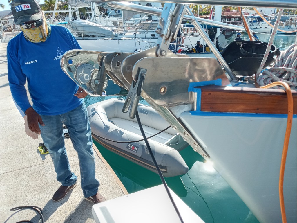
With the modifications finished, the fitting is substantially reinforced, extended well beyond the bow, and has a dedicated anchor point for the asymmetrical.

Do you have dimensions for the chain plates and backing plates. And who made them. I would like to bring the parts to Rio Dulce and have the carpenters there install the parts? I really appreciate your documentation of the process.
Joe
LikeLike
Hi Joseph. No, I don’t have the dimensions. The fabricator made them using the old ones and a process of test fitting. The fabricator is Sergio Galindo in LA Paz. He is however about to repeat the process on the 1985 P42 Gemini, starting April 1, so, I am guessing there is a possibility of him making a second set for you. I know he is super busy though.
LikeLike